Network designs
Represent a geographic network
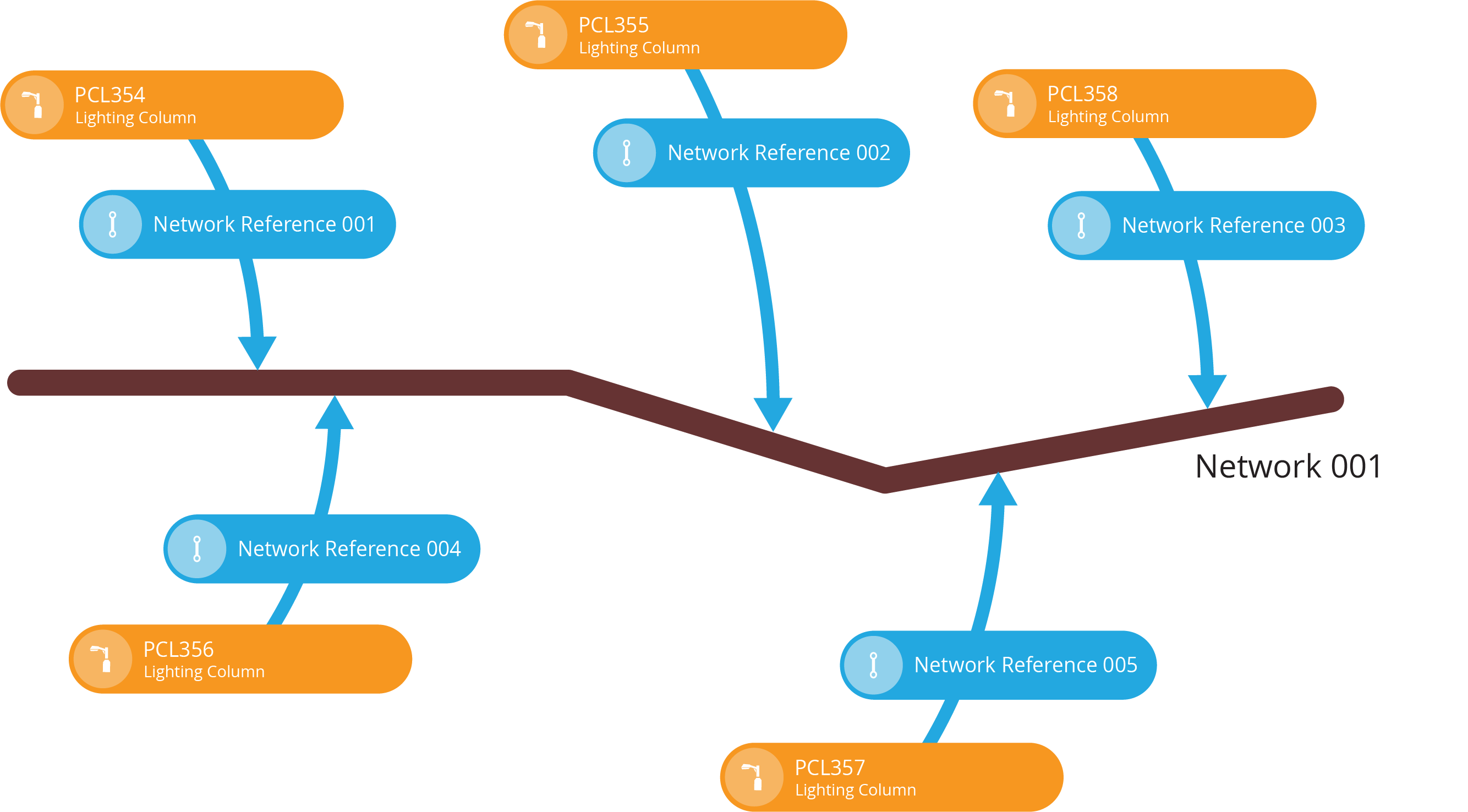
CausewayOne Asset Management lets you define networks of connected things. A network is comprised of network items with geometry, which each represent a part of the overall network geometry, e.g. road sections within a road network. You can associate assets with parts of the network by linking them to the relevant network item.
Networks can be visualised as layers on the map, enabling you to select anywhere within the network and see the relevant assets for the selected part, e.g. selecting a road to list the street lights on it.
To get started, you need to represent the network in CausewayOne Asset Management:
-
Create a design for the network.
-
Add attributes for any extra data points you want to record about each part of the network, e.g. a Street Name attribute for a road network. This may include implementing one or more interfaces to inherit their attributes alongside the ones on the design.
-
Create items of the network design to represent parts of the network.
-
Link asset items with network items via network references.
To learn more, see Networks.
If you import NSG/NLPG data, it will create all the necessary network designs and items for you! To learn more, see Gateway in Asset Classic.
Create a network design
To create a design that represents a network:
-
On the start screen, select Create design. If one is already open, select Create design in the top-right corner instead.
-
Choose the Network design type.
-
Fill in the details and then select Create design.
If you're unable to create a design, your user account may lack the required permissions.
Standard network design details
All network designs implement the Networks interface. Therefore, all network items inherit a standard set of properties and attributes. Required attributes are marked with an * asterisk.
Details
If left blank or unchanged, the network design will inherit the following properties:
-
Collections - network items can belong to the Live or Archive collections.
-
Geometry - is optional and all geometry types are allowed. You may want to make geometry required and/or limit the allowed types, e.g. only "Line" geometry for a road network.
-
Icon -
icon-network -
Colour -
#690095
Link attributes
The following Link attributes are inherited from the implemented interfaces:
-
Network References - links the network item to one or more assets via network reference items.
-
Reports - links to any generated reports involving the network item.
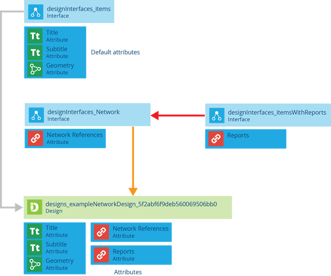
Interfaces
The following interfaces are inherited directly:
- Networks
The following interfaces are inherited indirectly via the above interfaces:
- Items With Reports
Diagram
Create network items
Once you have a design that describes a network, you can create items of that design to represent each part of the network's overall geometry.
To create an item of a network design:
-
On the start screen, select Designs and open the network design.
-
Select Create item in the top-right corner and choose the network design.
-
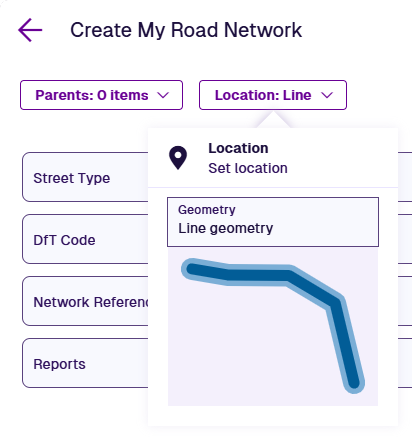
Select Location at the top . Select Geometry to open the Geometry Editor and use it to define the network item's geometry. Select Done to save.

-
You don't typically need to populate the Reports and Network References fields at this point. Fill in any other fields as needed.
-
Select Create to finish. To keep creating network items, enable Create another first.