Configuring an import
Specify how the data should be imported
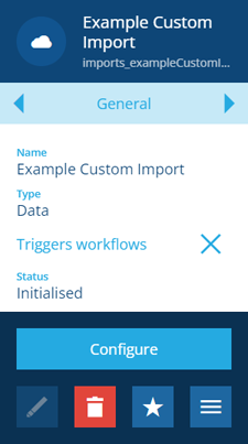
Once you've created an import and its Status is Initialised, you can proceed to configure it. This determines how the data should be interpreted and what to do with it! Specify the destination design and decide whether existing items will be updated, deleted or remain untouched.
Start the process
To start configuring an import:
-
Open the Gateway dashboard card and choose Imports.
-
In the Search panel, select the import item to view its details.
-
Select More in the action bar and choose Configure.
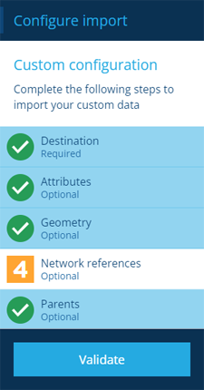
The configure import process
The key steps of this process will appear in the dashboard panel:
-
1 Destination - required
-
2 Attributes - optional
-
3 Geometry - optional
-
4 Network references - optional
-
5 Parents - optional
Fields marked with an asterisk * require a value to continue.
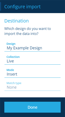
1 Destination
This is a required step. Fill in the following fields:
-
Design * - choose the design that you wish to update or replace the data on.
-
Collection * - choose the collection that the created/edited items will belong to.
-
Mode * - choose one:
-
Insert - new items will be created for each import data row. No existing items will be modified.
-
Update - existing items will be updated with matching import values. No new items will be created.
-
Merge - existing items will be updated with matching import values. New items will be created where a match isn't found.
-
Replace - all existing items will be deleted. New items will be created for all import data rows.
Update and Merge mode fields
These modes involve editing existing items, so choosing either will display extra fields. They determine how the import data rows get matched to any existing items of the destination design.
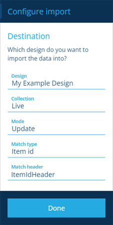
Match by Item ID
- Match type * - choose Item id.
- Match header * - choose the column header in your file that contains Item ID values (one per row). When each row is processed, its values will be applied to the item with that ID.
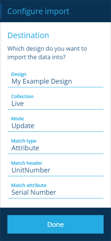
Match by attribute value
- Match type * - choose Attribute.
- Match header * - choose the column header in your file that contains the values you want to match on. When each row is processed, any items that contain the row's value for this column in their Match attribute will be edited accordingly.
- Match attribute * - choose the attribute in the destination design that you want to match on.
-
Select Done to choose the next step.
Replace mode will delete all items of the chosen design and collection before creating the new items. This is irreversible, so please double-check that you want to do this! We recommend contacting Support for advice before using this mode.
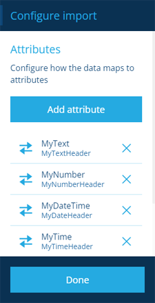
2 Attributes
This is an optional step. It associates the column headers in your file with corresponding attributes on the destination design, so it's clear where each value is supposed to go. Ensure each column header is formatted correctly for its intended attribute (e.g. a Number attribute won't accept a text value).
Gateway tries to create these associations automatically and often succeeds! The closer the names of your column headers and attributes, the more likely they'll be detected. Select the orange box to add them to the list.
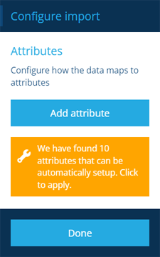
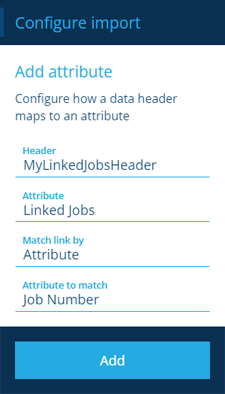
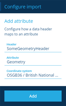
To manually add an attribute, select Add attribute. Fill in the following fields and then select Add:
-
Header * - choose the column header in your file containing the values you want to apply to the Attribute.
-
Attribute * - choose the attribute on the destination design to receive the Header values.
Link attributes
Link attributes have some extra fields:
- Match link by * - choose one:
-
Item Id - choose this if the Header contains Item ID values.
-
Attribute - choose this if the Header contains other values. If any compatible items exist that contain the same value in their Attribute to match, the item will be added to the Link attribute on the imported item.
-
In the screenshot, MyLinkedJobsHeader is a column header that contains job number values. Linked Jobs is a Link attribute for items of any design that implements the Jobs interface. When each import row is processed, any job items with a matching Job Number attribute value will be added to the Linked Jobs attribute on the imported item.
Geometry attributes
Geography attributes have an extra field:
-
Coordinate System - specify the system used by the geometry. Either populate the field with a custom proj-string or select and choose one of these:
-
OSGB36 / British National Grid - view on epsg.io
-
WGS84 Metres - view on epsg.io
-
WGS84 Lat/Lng (default) - view on epsg.io
-
NZGD2000 / New Zealand Transverse Mercator - view on epsg.io
In CausewayOne Asset Management, all geometry is saved using WGS84 Lat/Lng. If your geometry is different, it'll be transformed:
Custom grid shifts
By default, a simple Helmert transformation is used to convert imported geometry to WGS84 Lat/Lng.
To apply a specific transformation instead:
-
Upload the relevant grid shift file to CausewayOne Asset Management. Supported formats: GSB, LLA, DAT. Max size: 100MB.
-
Populate the Coordinate System field as above.
-
Append the string with
+nadgrids=<AlloyId>, where<AlloyId>is the Item ID of the uploaded grid shift file.
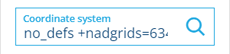
For example, if your geometry is OSGB36 British National Grid, you may want to supply an OSTN15 grid shift file for the transformation to WGS84 Lat/Lng.
-
Do this for custom geometry attributes. For the standard Geometry attribute present on all items, refer to the 3 Geometry step of the process instead of adding it here.
To remove an association from the list, select its button. Select Done to choose the next step.
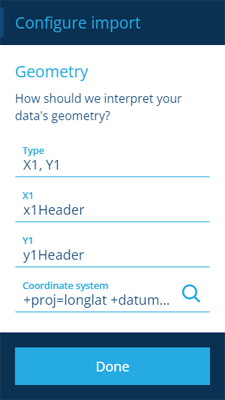
3 Geometry
This is an optional step. It lets you specify the format of the geometry values that will be applied to the standard Geometry attribute of the imported items.
X1, Y1
If your file contains Point geometry values split across two columns, select the Type field and choose X1, Y1. The following fields will appear:
-
X1 - choose the column header in your file with the X coordinate values.
-
Y1 - choose the column header in your file with the Y coordinate values.
-
Coordinate System - specify the system used by the geometry. Either populate the field with a custom proj-string or select and choose one of these:
-
OSGB36 / British National Grid - view on epsg.io
-
WGS84 Metres - view on epsg.io
-
WGS84 Lat/Lng (default) - view on epsg.io
-
NZGD2000 / New Zealand Transverse Mercator - view on epsg.io
In CausewayOne Asset Management, all geometry is saved using WGS84 Lat/Lng. If your geometry is different, it'll be transformed:
Custom grid shifts
By default, a simple Helmert transformation is used to convert imported geometry to WGS84 Lat/Lng.
To apply a specific transformation instead:
-
Upload the relevant grid shift file to CausewayOne Asset Management. Supported formats: GSB, LLA, DAT. Max size: 100MB.
-
Populate the Coordinate System field as above.
-
Append the string with
+nadgrids=<AlloyId>, where<AlloyId>is the Item ID of the uploaded grid shift file.
For example, if your geometry is OSGB36 British National Grid, you may want to supply an OSTN15 grid shift file for the transformation to WGS84 Lat/Lng.
-
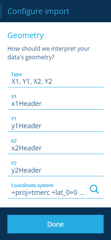
X1, Y1, X2, Y2
If your file contains simple LineString geometry values split across four columns, select the Type field and choose X1, Y1, X2, Y2. The following fields will appear:
-
X1 - choose the column header in your file with the X coordinate values for the start.
-
Y1 - choose the column header in your file with the Y coordinate values for the start.
-
X2 - choose the column header in your file with the X coordinate values for the end.
-
Y2 - choose the column header in your file with the Y coordinate values for the end.
-
Coordinate System - specify the system used by the geometry. Either populate the field with a custom proj-string or select and choose one of these:
-
OSGB36 / British National Grid - view on epsg.io
-
WGS84 Metres - view on epsg.io
-
WGS84 Lat/Lng (default) - view on epsg.io
-
NZGD2000 / New Zealand Transverse Mercator - view on epsg.io
In CausewayOne Asset Management, all geometry is saved using WGS84 Lat/Lng. If your geometry is different, it'll be transformed:
Custom grid shifts
By default, a simple Helmert transformation is used to convert imported geometry to WGS84 Lat/Lng.
To apply a specific transformation instead:
-
Upload the relevant grid shift file to CausewayOne Asset Management. Supported formats: GSB, LLA, DAT. Max size: 100MB.
-
Populate the Coordinate System field as above.
-
Append the string with
+nadgrids=<AlloyId>, where<AlloyId>is the Item ID of the uploaded grid shift file.
For example, if your geometry is OSGB36 British National Grid, you may want to supply an OSTN15 grid shift file for the transformation to WGS84 Lat/Lng.
-
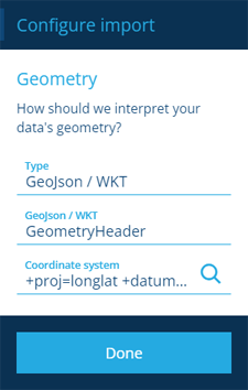
GeoJSON or WKT
If your file contains geometry in either format, select the Type field and choose GeoJSON or WKT. The following fields will appear:
- GeoJSON / WKT - choose the column header in your file with the geometry values.
-
Coordinate System - specify the system used by the geometry. Either populate the field with a custom proj-string or select and choose one of these:
-
OSGB36 / British National Grid - view on epsg.io
-
WGS84 Metres - view on epsg.io
-
WGS84 Lat/Lng (default) - view on epsg.io
-
NZGD2000 / New Zealand Transverse Mercator - view on epsg.io
In CausewayOne Asset Management, all geometry is saved using WGS84 Lat/Lng. If your geometry is different, it'll be transformed:
Custom grid shifts
By default, a simple Helmert transformation is used to convert imported geometry to WGS84 Lat/Lng.
To apply a specific transformation instead:
-
Upload the relevant grid shift file to CausewayOne Asset Management. Supported formats: GSB, LLA, DAT. Max size: 100MB.
-
Populate the Coordinate System field as above.
-
Append the string with
+nadgrids=<AlloyId>, where<AlloyId>is the Item ID of the uploaded grid shift file.
For example, if your geometry is OSGB36 British National Grid, you may want to supply an OSTN15 grid shift file for the transformation to WGS84 Lat/Lng.
-
Select Done to choose the next step.
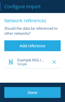
4 Network references
This is an optional step. To add imported items to an established network, you can define a reference to it here. For each import data row, Gateway will automatically create a Network References item that links the imported item to a matching Networks item (e.g. linking imported street lights to a street network). To learn more, see Referencing a network.
Select Add reference and choose a type:
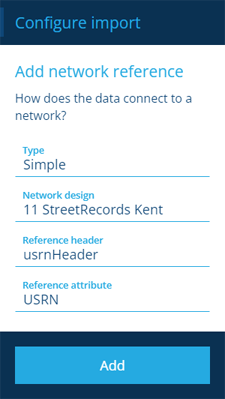
Simple
If your file doesn't contain chainage data, select the Type field and choose Simple:
-
Network design * - choose the design of the network that you want to link imported items to.
-
Reference header * - choose the column header in your file containing the matching values for the chosen attribute.
-
Reference attribute * - choose the attribute on the network design that serves as a unique identifier for each network item (e.g. for a street network, this could be the USRN of each street).
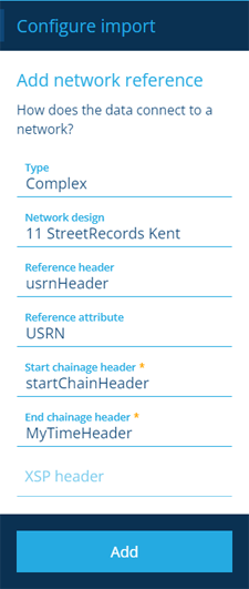
Complex
If your file contains chainage data, select the Type field and choose Complex:
-
Network design * - choose the design of the network that you want to link imported items to.
-
Reference header * - choose the column header in your file containing the matching values for the chosen attribute.
-
Reference attribute * - choose the attribute on the network design that serves as a unique identifier for each network item (e.g. for a street network, this could be the USRN of each street).
-
Start chainage header * - choose the column header in your file containing these values.
-
End chainage header * - choose the column header in your file containing these values.
-
XSP header - choose the column header in your file containing these values (if supported by your configuration).
To remove a reference from the list, select its button. Select Done to choose the next step.
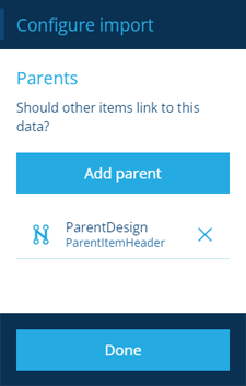
5 Parents
This is an optional step. If the imported items are related to existing parent items (e.g. imported components for parent assets), you can define their relationship here. For each import data row, parent items can be specified by supplying their Item ID or an attribute value. The imported item will be added to the chosen Link attribute on matching items of the chosen parent design.
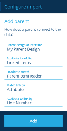
Select Add parent and fill in the following fields:
-
Parent design or interface - choose the design of the parent items you want to link from.
-
Attribute to add to - choose a compatible Link attribute on the parent item.
-
Header to match - choose the column header in your file that contains the Match link by values.
-
Match link by * - choose one:
-
Item Id - choose this if the Header to match contains Item ID values. Each imported item will be added to the chosen Link attribute on the corresponding item.
-
Attribute - choose this if the Header to match contains other values. If any compatible items exist that contain the same value in their Attribute to match, the imported item will be added to their Attribute to add to.
-
Match link by attribute
In the screenshot, ParentItemHeader is a column header that contains number values. For each import data row, one or more items of My Parent Design will be considered parents if they contain a matching value in their Unit Number attribute. The imported item will be added to the Linked Items attribute on those parent items.
To remove a parent from the list, select its button. Select Done to continue.
Validate the import
After completing the relevant steps, select Validate to save your configuration.
Gateway will silently perform a test run of the import, to verify that all data values can be applied to your chosen destinations. A notification appears when validation has finished. Select it to refresh the import's details.
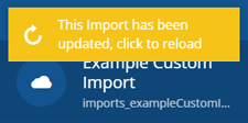
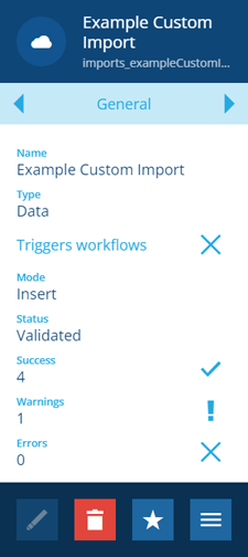
The import item now displays the number of data rows that were Successful and how many had issues.
If no Errors were detected, the validation was successful! You can proceed to commit the import when you're ready. While it's typically fine to proceed in spite of Warnings, we recommend checking the committed data afterwards, to make sure it's been saved as expected.
Otherwise, reconfigure the import and try again! You can download the test results to help troubleshoot any errors/warnings.